A versatile and compact antenna for fixed and portable operation!
Introduction
I’m a big fan of loop antennas, and you may remember my previous design from the October 2024 HARC News. Preparing for summer, I decided to create a new compact loop antenna to replace my usual wire antennas and verticals. After some experimentation, I finalized a design that covers the HF bands well, with much less size and weight. The advantages of the new design are:
- compact, lightweight and portable
- easily configurable for different operating situations
- can be easily supported on a desk, table or bench
- provides wide coverage of the HF bands from 7 MHz to 30 MHz
- no need for an internal (or other external) antenna tuning unit (ATU)
- low cost.
The antenna system comprises a loop integrated with a tuning and matching unit. The loop construction can utilize insulated stranded copper wire or lightweight copper tubing (refer to Figure 1). The system interfaces with a transceiver via a short length of standard 50 Ω coaxial cable, eliminating the need for additional tuning or matching configurations.

Tuning and Matching
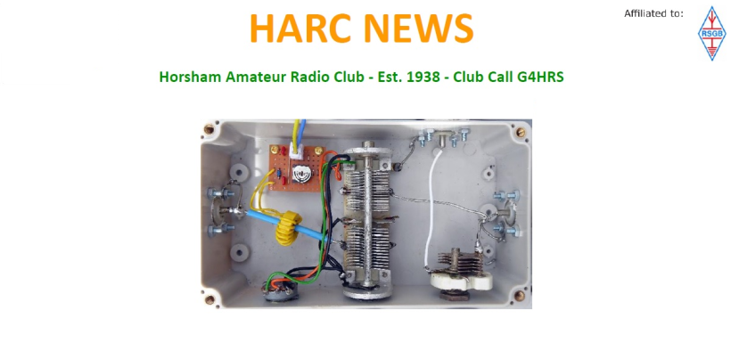
To facilitate mounting, the antenna tuning and matching have been relocated to the bottom of the loop, differing from the previous design. The tuning is achieved using a small dual-gang capacitor (VC1), while the matching to the coaxial feeder is accomplished through a 4 second variable capacitor (VC2). This approach is similar to that found in several well-known loop tuners manufactured by MFJ (refer to Figure 2).

To assist in tuning and eliminate the need for an in-line SWR meter, the tuning and matching unit includes a simple RF ammeter. The current in the loop is sampled by a small toroidal transformer (T1). The RF voltage from the secondary winding of T1 is sent to a Schottky barrier diode detector, and the rectified current is then supplied to a 1 mA moving coil meter (M1). RV1 and VR1 allow for calibration and sensitivity adjustment.
Construction
The tuning and matching unit is housed in a waterproof ABS enclosure measuring 156 x 90 x 60 mm, as shown in Figs.3 and 4. T1 is made using a ferrite ring placed over the conductor linking VC1b to SK2. The secondary winding (L2) has 10 turns of insulated solid wire. An additional insulated sleeve covers the primary (L1), which passes through the ring’s centre and secured with glue.
The internal RF and ground wiring employs 18-gauge tinned copper wire, while the connections to VR2 are made using insulated solid hook-up wire. Figure 5 illustrates the stripboard layout utilized for the RF detector, which is supported by two small brass pillars.


Components
The tuning and matching unit uses the following components:
- C1, C2 :10n 50V ceramic
- D1 BAT24 Schottky barrier diode
- M1 1 mA miniature panel meter
- RV1 47k miniature skeleton pre-set
- SK1-SK3 SO-239 connectors
- T1 Ferrite ring (see text)
- VC1 100 pF or 120 pF dual-gang air-spaced variable capacitor
- VC2 50 pF air-spaced variable capacitor
- VR1 10k linear carbon variable resistor

Loop construction
The antenna can be used with a variety of loops. The copper loop shown in Fig.1 was built from 3 mm copper tubing soldered at each end to a PL-259 connector. Note that the cooper is soldered both to the inner and outer screens of the connector and this is best done using a small gas torch since most soldering irons will be unsuitable for this job! To enhance safety (avoiding risk of contact with the loop during operating periods) the copper loop is enclosed in a short (7approx. 2 m) length of flexible plastic water pipe. Note that this should be fitted before soldering the second PL-259 connector in place!
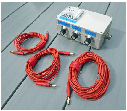
An alternative solution is the use of one or more lengths of insulated copper wire fitted with standard 4 mm banana plugs (these will connect directly to the inner conductor of the two SO-239 sockets). The three loops shown in Figure 7 provide complete coverage from 7 MHz to 30 MHz with each loop covering several amateur bands.
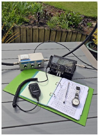
Depending on the operating environment the stranded wire loop can be supported in many ways. Small trees, garden parasols, and outbuildings can all provide suitable anchor points while operating outdoors. Clothes pegs, jubilee clips and gel-suction hooks can be used indoors to secure the wire to windows, doors and other flat surfaces. Fig.8 shows three different configurations successfully used by the author.

Testing and adjustment
Although designed for QRP portable operation (less than 5 W) the antenna has been tested with input powers of up to 30 W. Adjustment is straightforward and the following procedure is recommended:
- Switch to receive, adjust the receive volume and RF gain for normal operation
- Set up the loop and connect the tuning and matching unit
- Set VC2 to mid-position (2.5) and adjust VC1 for maximum noise (there will be a notable increase in noise when the loop is resonant)
- Set the transceiver’s RF output power to between 3 W and 5 W
- Set VR1 to mid-position and transmit a steady carrier.
- Observe the meter display and re-adjust VR1 for an indication of between 0.6 and 0.8 mA
- Carefully re-adjust VC1 for maximum current and then adjust VC2 for maximum indication
- If necessary, repeat step 6 until the maximum value of RF current is indicated. This will usually correspond to maximum radiated power and minimum VSWR.


Safety
Since high RF voltages and currents are present (even when using relatively low power) it is vitally important to observe the relevant safety precautions when using loop antennas. It is also essential to be aware that intense RF fields can be present in the immediate vicinity of a radiating loop. When using a loop antenna:
- Use minimum power when tuning the antenna (less than 5 W)
- Avoid contact with the loop and connectors when in use
- Keep a safe distance from the loop whenever it is active (more than 2 m)
- Remember that very high voltages and currents are always present when the antenna is in use!
In use
With any antenna, the proof of the pudding is only confirmed through practical use so I was delighted when R9CA in Asiatic Russia (more than 4,700 km away) replied to my very first CQ call with a “599” report (see Fig.11). Not bad for 3 W and 3 m of wire!

For more information please visit our online store or alternatively contact us and our team will be happy to assist you!
Credits - Mike G8CKT