An RF choke on your antenna feedline will secure your radio against random RF currents, protecting your electrical devices and yourself from tingling or even minor burns.
You may not be experiencing any issues with your radio at the moment. However, it is still a good idea to have an RF choke, especially in field operations where you can't control the entire communications and antenna system.
Some antenna configurations are prone to stray RF currents. An RF choke is always a good idea if you change antennas regularly.
These components are not too costly, but they are also easy enough to make for those who prefer to be self-reliant. Here, we offer an easy guide for creating a DIY RF choke.
What Do You Need to Make an RF Choke?
An RF choke is simple to make and will cost no more than a few pounds for all the materials. Some of the items needed may even be easy to find around the home.
- Small plastic box — avoid metal; the box should have two RF connectors, one at each end.
- A toroid— a small doughnut-shaped conductor with a coil around it. FT-114-31 is a good specification.
- A coaxial cable — also referred to as coax; coax is a transmission line used to carry high-frequency electrical signals. Coax usually consists of an inner conductor, commonly copper, protected by a conducting shield with the two separated by an insulating material. The set-up has a plastic coating for protection.
Besides the choke components, you'll also need to assemble the following tools:
- A sharp knife
- Small pliers
- A regulation soldering iron
- Tweezers
- Electrical continuity tester
Step-by-Step Guide on How to Make an RF Choke
1. Trim the Coax Cable
Prepare the wire by removing the insulation from one end of the coax cable with a sharp knife. Remove about one centimetre of the protective plastic coating.
Be careful not to cut too deep, which will damage the braid beneath the outer layer. You can feel the knife as it cuts through the plastic and starts to grind on the copper.
Once you've cut around the coating, slide it off the cable using a small pair of pliers.
2. Prepare the Braid
Using your fingers, carefully separate the exposed braid, working from the centre.
3. Remove Some Insulation
Remove a small amount of insulation from the exposed wire at the tip. Proceed carefully as it is easy to just cut the wire off by mistake. Removing the insulation will make it easier to solder later.
4. Solder the Exposed Ends
Solder the exposed ends of the wire. We advise brushing up on soldering safety if you haven’t used a soldering iron before.
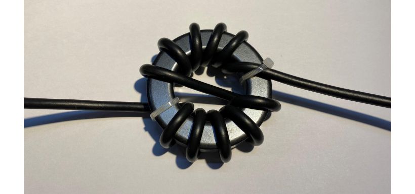
5. Wind the Coax Around the Toroid
Wind the coax around the toroid. Feed the long untrimmed end through first, leaving enough length at the soldered end to fit the box.
Whether the wire is of sufficient length is a judgement based on the available space within the box once the toroid is in place between that and the RF connectors.
Every time the wire goes through the core of the toroid counts as one turn. The length of the wire and the number of turns will depend on the coax and the frequencies.
Make the coax snug around the toroid but don’t make it so tight that you create a kink or ridge in the wire. The coax should not be loose, but it can cause problems if it is too tight and the wire may become damaged.
Ensure the wire has enough space around it and is not squeezed up against itself on the toroid. The coax should cover three-quarters of the toroid when you have finished.
If the turns of the coax become loose as you are winding, you can use plastic tie wraps to help keep it stable. Use a small cable tie to secure the first turn which will help hold the start point whilst the rest is wound. You can also secure the last turn if you wish.
6. Prepare the Other End of the Coax
Once the coax is securely wrapped around the toroid, repeat the process at the other end of the coax.
Carefully remove a section of plastic using a knife and pliers. Spread the braid and take off just a little insulation from the top.
7. Fit the Toroid into the Box
Fit the toroid into your plastic box. It is usually a tight fit.
8. Connect the Coax to the RF Connectors
Connect the coax to the connectors using the soldering iron. This step is where a pair of tweezers can help position the wire in the box. There will not be much space to solder and, because the box is plastic, it could melt if your technique is not very accurate!
9. Check for Continuity
Once the soldering is complete, check the box for continuity using the electrical continuity testers.
An electrical continuity tester is necessary to check that the current flows between the two RF connectors once you've fitted the RF choke.
If you have an antenna analyser and dummy load, you can use these to check the RF choke. Usually, a flat line is something you don’t want to see, but, in this case, it means you have done the job correctly.
10. Finish Off the Job
You can add plastic ties to insulate the toroid. Some people hot glue the plastic ties once everything is in place to ensure that the toroid and/or the plastic don’t move.
Don’t use epoxy glue: a simple hot glue is often used and won’t disturb the magnetic field.
If you have any questions about the safety of your work, then consult a registered electrician.
Conclusion
Operating a radio without an RF choke puts the set's electronics at risk and can impact tuning and reception quality.
Making your own RF choke is an easy project, even if you are a novice and have never done anything like this before. Follow the steps above for a more secure connection.
One final point to note is that RF Chokes are best installed at the feedpoint of the antenna and not behind the radio in the shack.
Good luck.