As an antenna designer, I'm always fascinated by the seemingly endless possibilities of shaping metal and wire to capture radio waves. I spend my days working on complex, high-performance antenna systems, both for my own company, InnovAntennas, and in collaboration with companies like Moonraker. But sometimes, the simplest designs are the most intriguing. There's a certain elegance and satisfaction in taking readily available materials and turning them into a surprisingly effective antenna. That's what drew me to the "flower pot" antenna – a classic design that's popular among radio amateurs for its ease of construction, low cost, and stealthy appearance. In this post, I'll share my own experience building and testing flower pot antennas for the 2m and 4m amateur bands, combining practical build details with the underlying theory.
Why the Flower Pot?
Even for an experienced antenna designer, there's something appealing about the flower pot antenna's simplicity. It's a vertically polarized, end-fed half-wave dipole, typically housed inside a non-conductive tube – often, but not always, an actual flower pot! The "flower pot" name is more about its unassuming appearance than its required construction materials. It's a design that proves you don't need expensive materials or complex tools to get on the air.
For me, building a flower pot antenna was a bit of a busman's holiday. It was a chance to step back from the CAD software and computer simulations and get back to basics, using my hands and a few simple tools to create something functional. I also enjoy pushing technology and understanding its limitations, something easily done with simple antennas such as this. And, let's be honest, there's a certain satisfaction in building something yourself, especially when it works well!
Beyond the fun factor, the flower pot antenna has some practical advantages. It's relatively inconspicuous, which can be important in locations with antenna restrictions. It's also weatherproof (when built properly) and doesn't require a separate ground plane or radials, making it convenient for portable operation or temporary installations. I could see myself using one of these as a backup antenna at my home QTH, or taking it along on a portable operating trip.
The Theory Behind the Bloom
Before we dive into the build details, let's take a quick look at the theory behind the flower pot antenna. It's essentially an end-fed half-wave dipole, but with a clever twist that makes it work without a traditional ground plane.
A standard half-wave dipole, as you probably know, is a resonant antenna with two elements, each approximately a quarter-wavelength long, fed at the centre. An end-fed half-wave antenna, as the name suggests, is fed at one end. The problem with end-feeding a half-wave antenna is that the impedance at the end is very high (thousands of ohms), making it a poor match for the 50-ohm impedance of typical coaxial cable and transceivers.
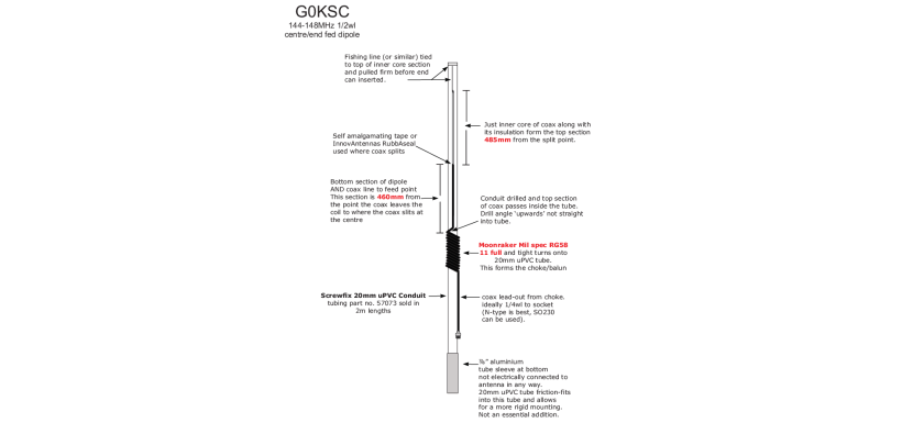
The flower pot design addresses this in a couple of ways. Firstly, the design is a coaxial dipole. The top section is a half-wave in total length, and this section is made up of two parts. The top quarter-wave uses the centre conductor of the coaxial cable, and the bottom quarter wave uses the inside of the coax braid.
The second crucial element is the choke balun. This is typically formed by coiling a section of the coaxial cable itself near the feed point. The choke presents a high impedance to RF currents that would otherwise flow on the outside of the coax shield. Without the choke, the entire length of the coax feedline would become part of the antenna, leading to unpredictable radiation patterns, RFI in the shack, and a high SWR. The choke forces the RF current to flow on the inside of the coax braid up to the feedpoint, and then onto the radiating element (the extended inner conductor). This is a very common misconception with flower pot antenna builders, who do not put the choke on, as it is hidden inside the tube!
The coiled coax choke effectively isolates the radiating element from the feedline, allowing a more predictable current distribution and a radiation pattern similar to a conventional dipole.
Finally, the antenna is vertically polarized, which is often preferred for FM and repeater operation on VHF bands like 2m and 4m.
Building the 2m Flower Pot Antenna: A Step-by-Step Guide
For my 2m flower pot antenna, I targeted a centre frequency of 145 MHz, the middle of the UK 2m amateur band. Here's what I used:
- Coaxial Cable: Moonraker RG-58 mil-spec coax (approximately 2 meters). I chose RG-58 because it's readily available, relatively inexpensive, and has a well-defined velocity factor.
- Housing: 20mm white plastic waste pipe from Screwfix (for the 2m version). This is a great option because it's cheap, readily available, and weather-resistant.
- 22mm fibreglass tube (for the 4m version, for added rigidity).
- Heat Shrink Tubing: Large diameter heat shrink tubing to cover and protect the finished antenna.
- Tools: Soldering iron, solder, wire cutters, measuring tape, utility knife, heat gun.
Design Calculations:
The first step is to calculate the length of the radiating element. The basic formula for a half-wave antenna is:
Length (meters) = 143 ÷ Frequency (MHz)
However, we need to adjust this for the velocity factor of the coaxial cable. The velocity factor represents how much slower radio waves travel through the coax compared to their speed in free space. RG-58 coax typically has a velocity factor of around 0.66. So, the adjusted formula becomes:
Length (meters) = (143 ÷ Frequency (MHz)) × Velocity Factor
For 145 MHz and a velocity factor of 0.66, the calculation is:
Length (meters) = (143 ÷ 145) × 0.66 ≈ 0.65 meters (65cm)
So, the total length of the half-wave dipole is 65cm.

Image: Antenna start point is the choke just above my hands in the photo. I used the full sections length sin each case to give additional height when mounted.
Construction Steps:
- Cut the Coax: I cut a length of RG-58 coax slightly longer than needed (around 2 meters), to allow for the choke and some extra length for trimming.
- Prepare the Radiating Element: I measured 65cm from one end of the coax. At this point, I carefully stripped away the outer jacket and the braid, exposing the inner conductor. This exposed inner conductor forms the top quarter-wave section, and the coax braid still attached will form the bottom half. Accuracy is important here!
- Form the Choke: About a quarter-wavelength (32.5cm in this instance) down from the point where I stripped the braid, I formed the choke by coiling the coax. Typically, online resources and guides suggest around 6 turns for a VHF choke. However, the optimal number of turns can vary depending on the specific coax type, the diameter of the coil, and even the surrounding environment. In my practical experience, using the 20mm plastic waste pipe as a former and the Moonraker RG-58 mil-spec coax, I found that 11 turns provided the best results, giving the lowest SWR and the sharpest dip at the target frequency. I temporarily secured the coil windings in place using some good quality insulation tape. Don't be afraid to experiment here; the key is to find what works best for your specific setup.
- Connect Braid to Inner: At the point where I started the coil, I soldered the braid to the inner conductor.
- Assemble: I then slid the plastic pipe over the coax, positioning the choke near the bottom.
- Initial Testing: This is where the fun begins! I connected the antenna to my NanoVNA, a very handy piece of test equipment for antenna work. I took an initial SWR reading across the 2m band.
- Tuning the Choke: My initial reading showed the SWR dip (the point of lowest SWR) was a bit too low in frequency. I carefully adjusted the number of turns on the choke, adding or removing turns in small increments, and re-measuring the SWR each time. The goal is to get the SWR dip as close as possible to your desired centre frequency (145 MHz in this case). The coil acts as an impedance transformer.
- Tuning the Length: Once I was happy with the choke, I focused on fine-tuning the centre frequency by adjusting the overall length. I carefully trimmed small amounts of coax from above the choke coil. This slightly changes the overall electrical length of the antenna, shifting the resonant frequency.
- Iterative Process: Tuning is an iterative process. It's a bit of a dance between adjusting the choke and trimming the length, constantly checking the SWR and resonant frequency with the NanoVNA.
- Heat Shrink: Once I was satisfied with the SWR and resonant frequency (I achieved an SWR of better than 1.2:1 at 145 MHz, with a 1.5:1 bandwidth of about 2 MHz), I covered the whole assembly, except for the radiating element and a section of coax at the base for connection, with large diameter heat shrink tubing. This provides weather protection and adds mechanical stability to the antenna.
Important note: The heatshrink will change the resonant frequency of your antenna. Therefore, best to get an indication of SWR before the heatshrink is applied.
Building the 4m Flower Pot Antenna
The process for the 4m flower pot antenna was very similar, just with different dimensions. The 4m band in the UK is centred around 70 MHz.
Using the same formula:
Length (meters) = (143 ÷ Frequency (MHz)) × Velocity Factor
Length (meters) = (143 ÷ 70) × 0.66 ≈ 1.35 meters (135cm)
So the length of radiating element, braid stripped away, is around 67cm.
I followed the same construction steps as for the 2m version, adjusting the choke turns and overall length to achieve a good SWR on 4m. I found that the 4m version was a bit more sensitive to the choke dimensions, but with a bit of patience, I was able to get a good match.
Crucially, because of the increased length and potential for flexing, I used a 22mm diameter fibreglass tube for the main support, instead of the 20mm plastic waste pipe. This provides much better rigidity and prevents the antenna from drooping or bending in the wind. The fibreglass tube is still lightweight and non-conductive, so it doesn't interfere with the antenna's operation.
On-Air Performance
I've been very pleased with the performance of both flower pot antennas. They're surprisingly effective, especially considering their simplicity. I've made numerous local contacts on both bands, and I've even managed a few longer-distance contacts under good conditions. Of course, they're not going to compete with a multi-element Yagi, but for their size and cost, they perform admirably.
Conclusion: A Classic for a Reason
The flower pot antenna is a classic design for a reason. It's easy to build, inexpensive, and delivers surprisingly good performance. It's a great project for beginners, but it's also a fun and rewarding build for experienced hams like myself. It's a reminder that sometimes, the simplest solutions are the best. And, let's face it, there's something inherently satisfying about making contacts with an antenna you built yourself, especially one that looks like it belongs in your garden rather than on your roof!
I encourage anyone interested in building their own antennas to give the flower pot a try. It's a great learning experience, and you might be surprised at just how well it works. You can, of course, find a range of coax cables at Moonraker, perfect for this project. And who knows, maybe you'll even discover the joy of antenna building and join the ranks of the "Pioneers of Radio" – even if it's just in your own back garden! What are your experiences with simple antenna builds? Have you ever built a flower pot antenna? Share your thoughts and results in the comments below!
For more information please visit our online store or alternatively contact us and our team will be happy to assist you!